Intermediate support for upper tray required on piperacks over 6096mm wide. Electrical Engineers seldom show interest acquiring knowledge and experience on cable tray installations.

Cad Drawing Electrical Cable Tray Layout Plan Legend
Single triad shielded signal.

. Cable tray laying to take care of necessary clearances for the fire proofing of structure. As part of our ongoing commitment to customer support Legrands cable management ranges and Cablofil wire mesh cable tray are now integrated into the following plant design modeling systems. All installation requirements and tolerances shall be in accordance with the technical specification the latest construction drawings and the applicable documents.
Single pair shielded thermocouple extension cables shall be used between thermocouple head and junction boxes transmitters local control panel mounted instruments. Hot lines and cold lines shall be kept apart in different groups on a tier. Single line diagram can be prepared when instrument cable schedules are available.
Instrument location layout is a layout which indicates the exact location of instrumentjunction box trenchtrays etc. PDMS Plant Design. Click in the Add Cable Trays dialog box.
IC design basis covers below listed technical details as minimum Standard for representation of field Instruments and control in PID diagram in accordance to ISA S51 S52 and S53. Trench and duct is the path for primary cable and tray is the path for secondary cables. Vertical cable tray elbows at the top of runs should be supported at the joint on each end.
The design installation and protection of wire and cable systems in substations are covered in this guide with the objective of minimizing cable failures and their consequences. Instrument cable wiring schedule. For an example see the above graphic.
These guidelines and information do not intend to cover all details or variations in cable tray systems nor provide for every possible installation contingency. The popular list of instrumentation modeling software is as follows. E3D Everything 3D by Aveva.
Cable tray systems design shall comply with NEC Article 392 NEMA VE 1 and NEMA FG 1 and follow safe work practices as described in NFPA 70E. A proper and professional way of cable tray installation requires good involvement and coordination of people from both electrical and mechanical disciplines. In the Cable Tray Layout Preferences dialog box on the Routing tab select Automatically create riser at new Elevation.
Label Rule Each cable tray support is labeled with the corresponding name from the model. Cable Management 3D Modeling Tools. Field cut cable tray length as required.
Generally the top tier is to be kept for Electrical cable trays if not provided in underground trench and Instrument cable ductstrays. Instrumentation design course delivers 3D modeling 2D extraction Modifying equipment shapes Cable tray specification and Extraction of instrument location layout. Basic Requirements Related to Field Instruments and Cables.
What kind of electrical and instrument drawing can be found in fabrication of an oil and gas fabrication project. Graphic Rule This is an example of the graphic representation of a cable tray support in a plan view. If playback doesnt begin shortly try restarting your device.
Ensure uptime by trusting products specifically designed for the your application. Instrument wiring layout instrument air routing layout loop drawing jb layout cable schedule cable tray layout. Compatible with AutoCAD and Gstar-CAD.
Following are the steps to be done for laying cables on wall mounted cable tray. Click Preferences on the Properties palette. Instrument location plan drawing can be started to.
Fix the cable tray as. Acceptance testing cable cable installation cable selection communication cable. INSTRUMENT CABLES This specification covers the requirements for instrument signal cables thermocouple extension cables RTD cables and power control cables.
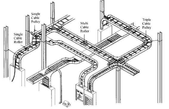
This only an overview and few drawing samples for who wants to know about a project fabrication -construction specially. A tray is either made of metals or FRP Fiber reinforced plastic. Install cable tray support using a pre-fabricated flange or GI channel.
In the Conduit Layout Preferences worksheet select Automatically create. Subcontractor shall submit actual cable tray drawing after installation for As-built. No matter the gauge size conductor count insulation jacket armor or rating you need Belden can accommodate your requirements.
Click OK and then enter an elevation in the Add Cable Trays dialog box. Reliabilityeven in the harshest of environmentsis the hallmark of Beldens instrumentation cables. 6 Cable Ladder and Cable Tray Systems Including Channel support Systems and other Associated Supports Definitions and Abbreviations Accessory Component used for a supplementary function eg.
The data files available are specifically for use with the relevant systems and as such cannot be used or converted. Material take-off for field instrument installation hardware. Paneldes Raceway software is for construction engineers with electro-mechanical design and cable management requirements such as those designing plant cable raceway ductbank cable tray and cable ladder layout and cable routing.
List of alarm points with settings and ranges. To join two components together clamp or fix to walls ceilings or other supports covers and cable retainers Associated supports Bespoke supports for cable. We can extract cable tray layout junction box layout instrument location layout bill of materials etc easily using 3D modeling software.
Instrument Layout and recommended cable tray routing drawing within battery limit Instrument installation drawing. CABLE TRAY MANUAL Based on the 2014 National Electrical Code Cable Tray Manual 2014 Cable Tray Manual B-Line series Cable Tray Systems MAN-1 Eaton Mark shown is the property of its respective owner. The final branch cable tray route shall be decided by subcontractor Field Engineer in accordance with the site condition.
- IEEE Guide for the Design and Installation of Cable Systems in Power Generating Stations ANSIIEEE Std 422-1986 Revision of IEEE Std 422-1 977 Published by The Institute of Electrical and Electronics Engineers Inc 345 East 47th Street New York NY 10017 USA April 4 1986 SH10447 WITHDRAWN. 48 2384 ratings 3259 students enrolled. Material take-off for instrument cables cable trays tray supports etc.
Most of them think its a concern of mechanical fabricators to be taken care of it. This cable tray support system drawing has Isometric view and cross-sectional view. As I described in the above diagram specification for field instruments DCS Safeguarding systems instrument standard drawing has to be completed prior to prepare the requisitions and inquiry report for field instruments cables etc.
The size length and intervals of the support to be as per the specification standards number of cables and size of the cable.
Typical Design Philosophy Of Cable Trays For Power Plant Electrical Engineering 123

Sample Drawings Of Power Distribution Projects Equipment Cable Tray Layout Services Consultants From Kolkata
Detail Engineering Protech Consultants Pvt Ltd
2

Cable Tray Installation Details With Pictures Paktechpoint
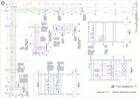
Detail Engineering Protech Consultants Pvt Ltd

Sample Drawings Of Power Distribution Projects Equipment Cable Tray Layout Services Consultants From Kolkata

Consultant Cad Drawings Equipment Cable Tray Layout Services In Whole World Id 3325849112
0 comments
Post a Comment